7-12-2026 WEEK 3
flops
tried soldering without flux and melted a wire stuck in my 24 neopixel ring rgbw data out.
tried to copy over all the test examples for the sensors to one aura_camera.ino file with arduino ide’s tabs, the qwiic connections were struggling to connect.
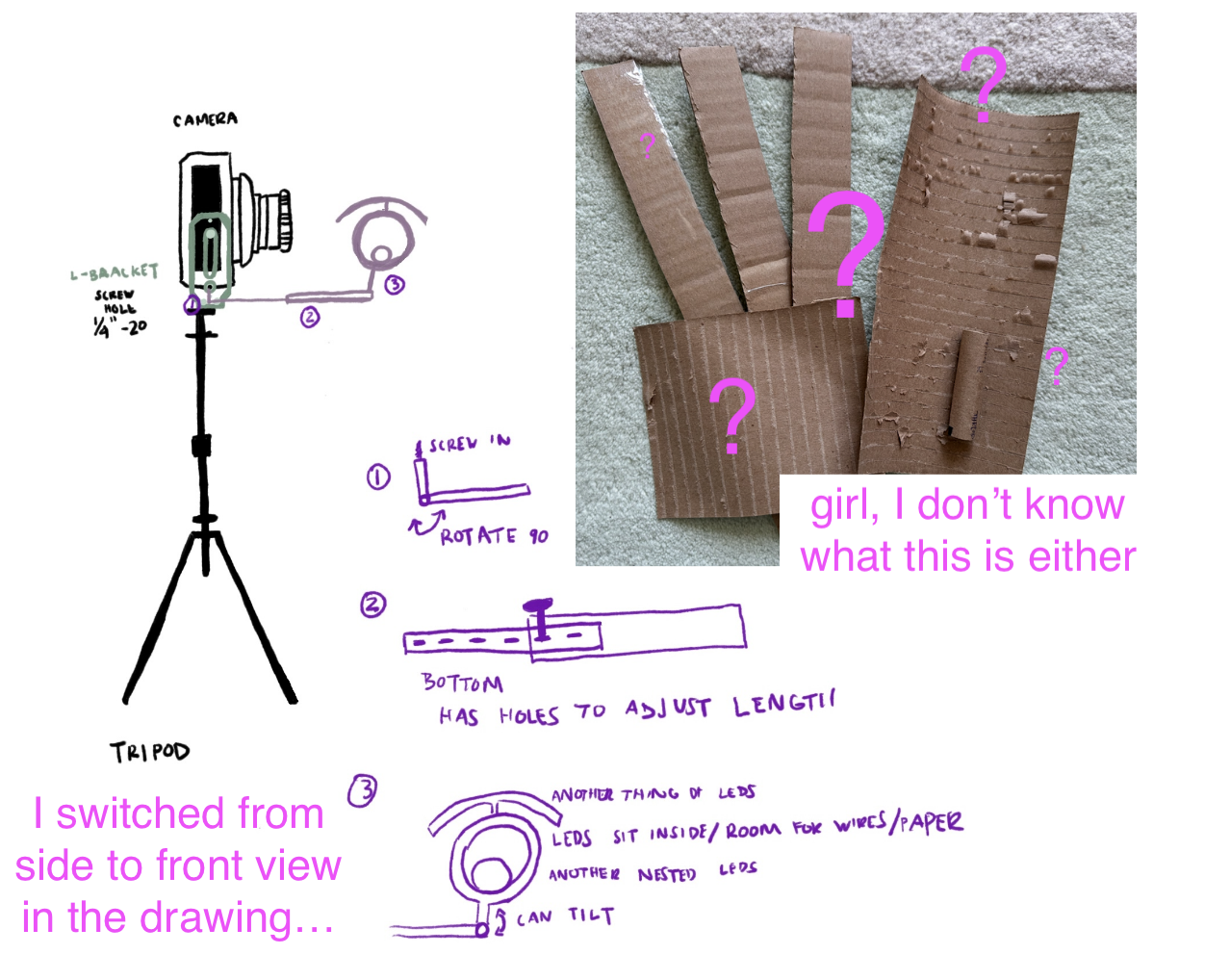
tried to prototype a 3d design for how the leds will be laid out with neopixel jewel rgbw, 24 neopixel ring rgbw, and ¼ of neopixel 60 ring rgbw segment, but cardboard is hard to make joints and telescoping.
realized when prototyping that the leds are just too far from the sensors and I need another microcontroller setup just for the sensors. figured out a bluetooth setup to send over the sensor data to the arduino uno r4.
ordered a bunch of electronic parts for the sensor setup, paused on soldering leds until flux comes, and ordered a magic arm clamp to help with led prototyping.
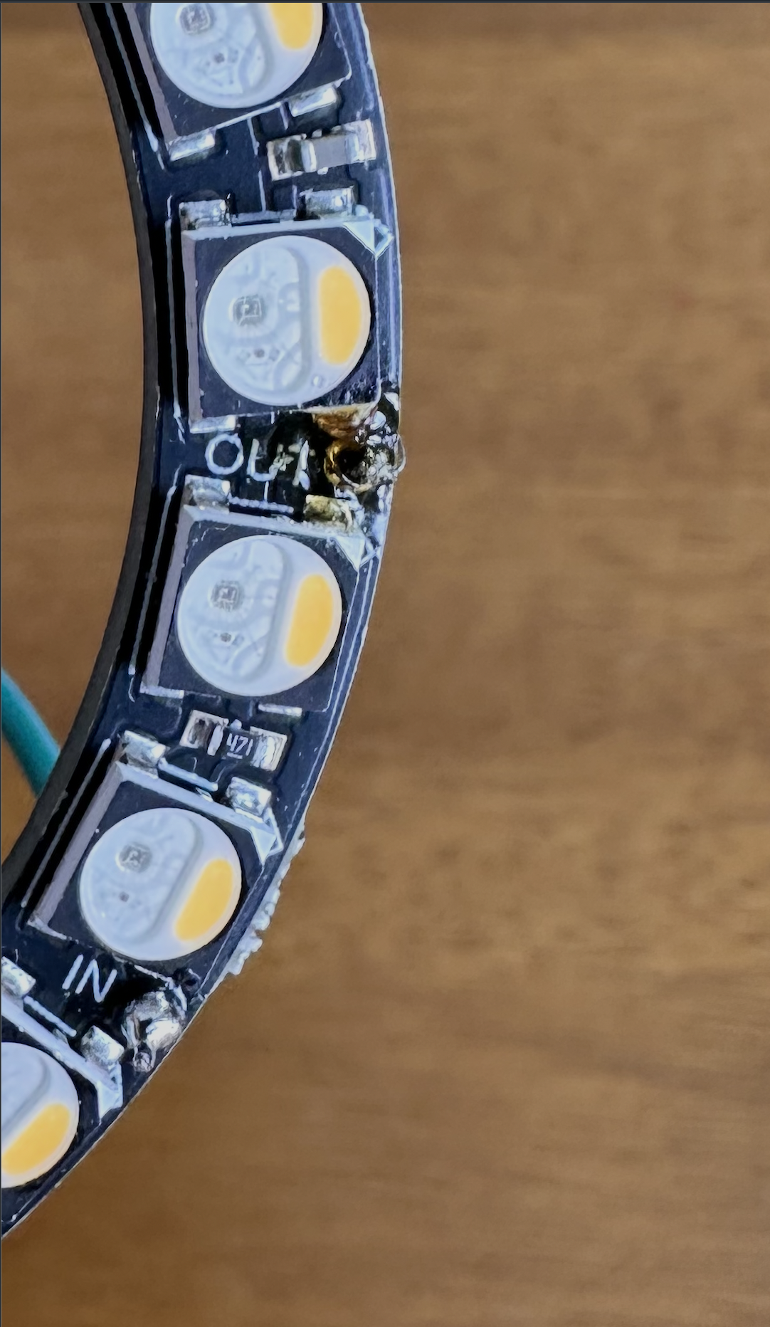
left: burnt guy
right: confused 3d prototyping plans
7-5-2026 WEEK 2
testing
soldered neopixels leds, so I can test out which ones would look the best for the photo. also testing out the black backdrop and multi exposure photos on the lomo. it’ll be lots of testing until flash/lighting settings, distance settings, diy vaseline on uv filter lens, and different leds types/settings. for testing purposes the neopixels will be directly connected to the arduino uno r4. code for testing out the leds can be found here
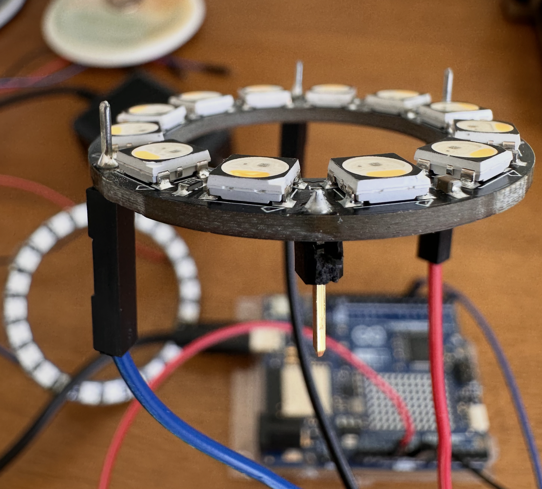
solderd male to male dupont cables for ground, power, and data in pads. soldered male header pin on the data out pad.
black backdrop stuck on the wall with command strips. a segment of my couch flipped 90 degrees and a couple of shoeboxes to boost up doughboy.
flash needs something in between, can play with distance to adjust or the exposure levels on the lomo camera.
experiments
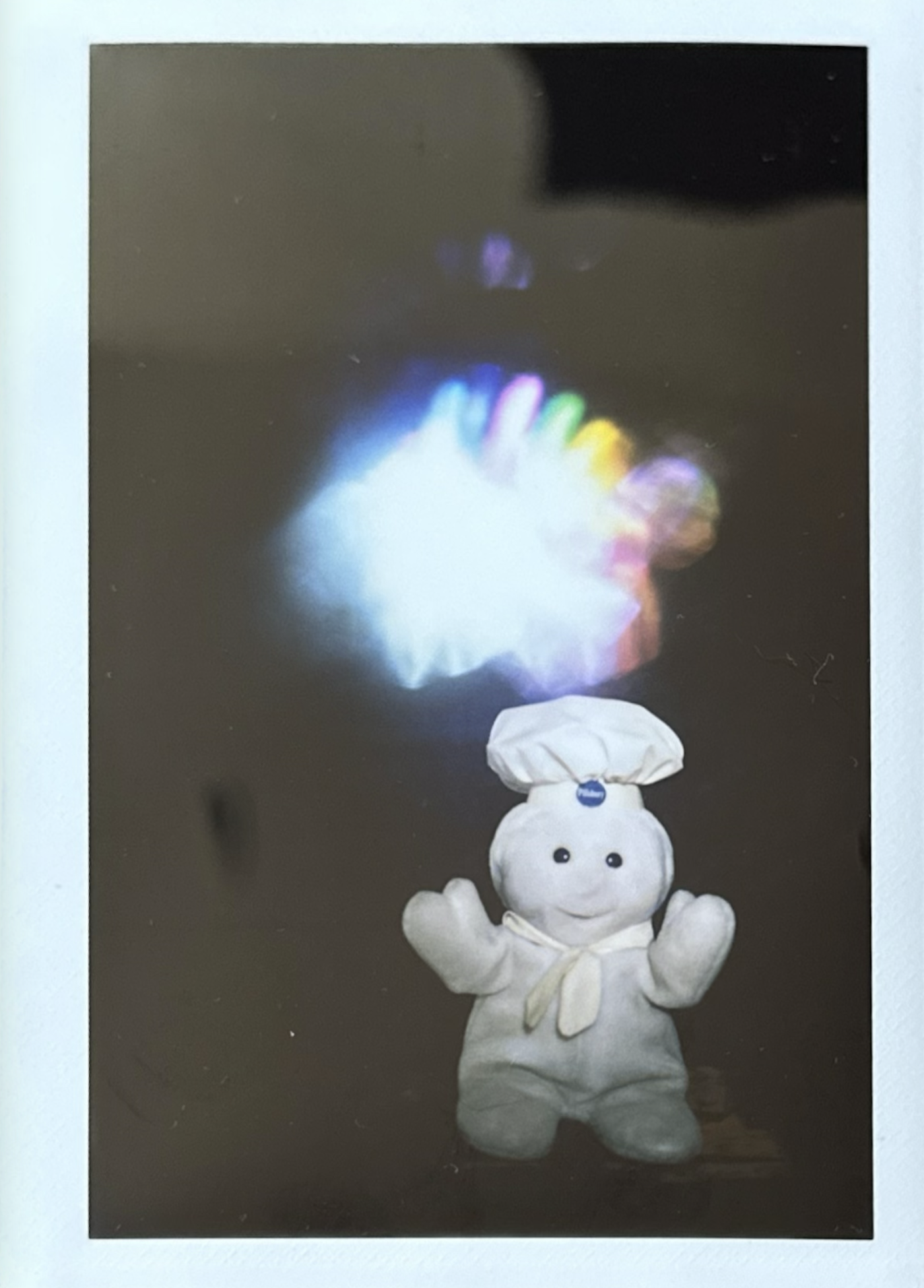
1. used 12 ring rgbw. included w channel and white from rgb. one in a row pattern. the white is overpowering. 7" away from lens. f22 used on camera for second led exposure
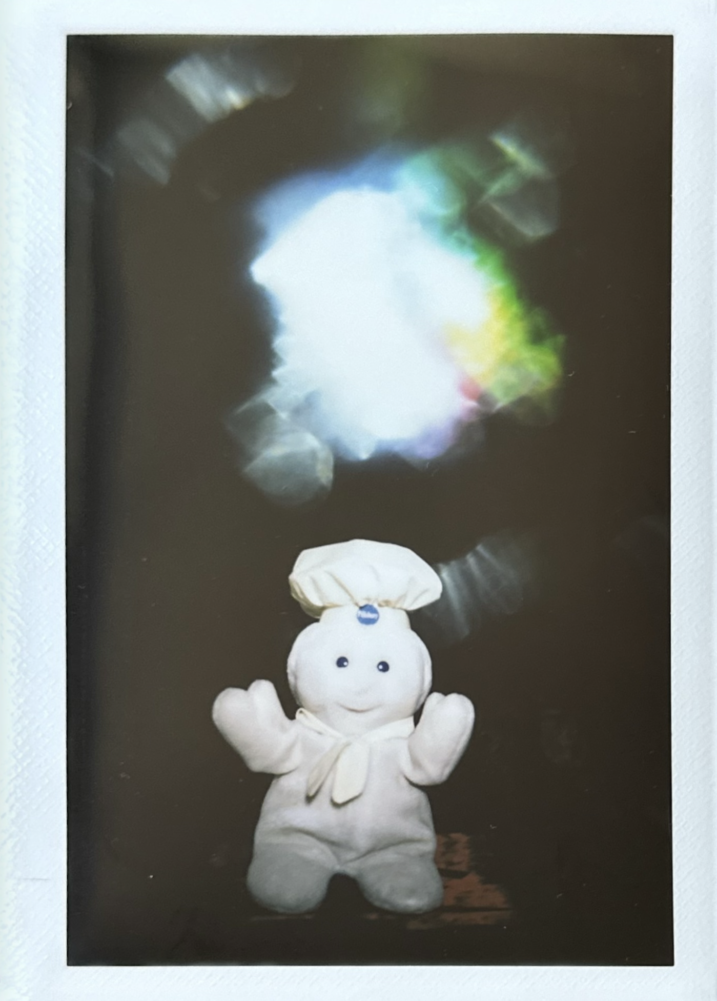
2. using 12 ring rgbw. one in a row pattern including whites. more vaseline added to lens filter. 7" away from lens. f22 used on camera for the second led exposure
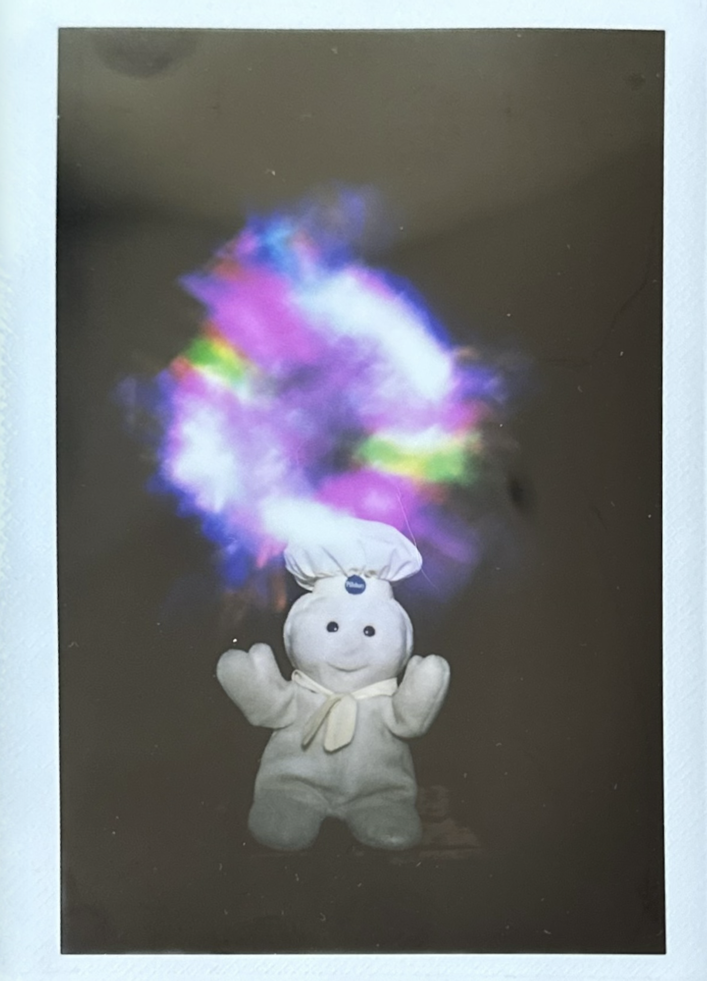
3. used 24 ring rgb. one in a row pattern. 7" away from lens. reduced led brightness to 15

4. used 24 ring rgb. no white included. two in a row pattern. 7" away from lens. used bulb mode on camera for second exposure. reduced led brightness to 5. indigo color is hard to see
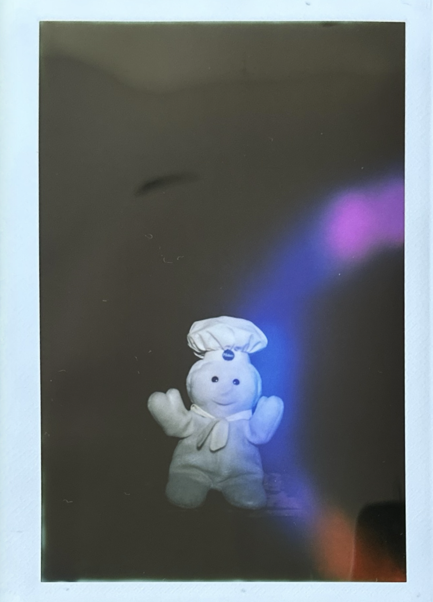
5. used 24 ring rgb. two in a row pattern. new indigo setting. held as close as possible to lens. used bulb mode on camera. led brightness 5
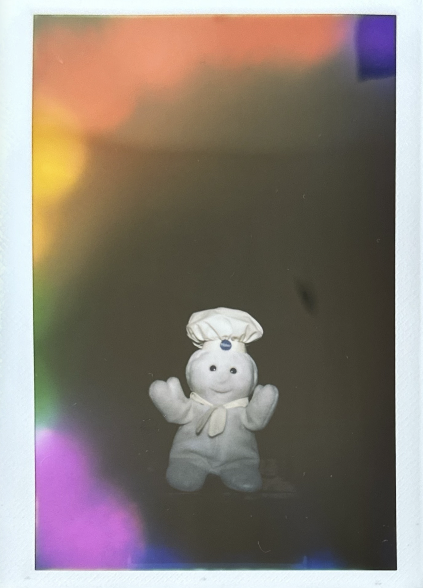
6. used 24 ring rgb. two in a row pattern. held as close as possible. bulb mode. led brightness 8
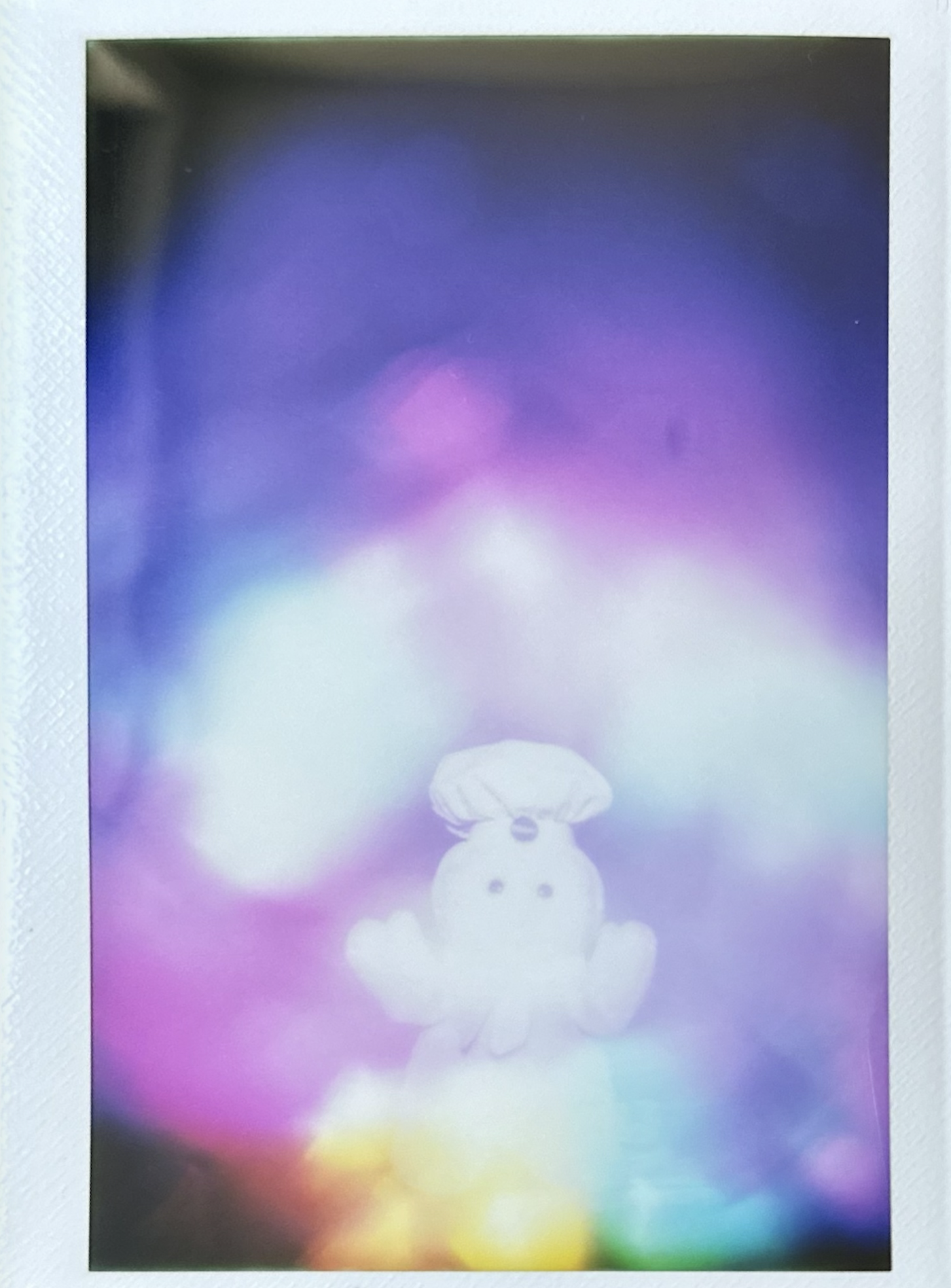
7. used 24 ring rgb. black gaps pattern. 4" away from lens. used f22 on camera. led brightness 35
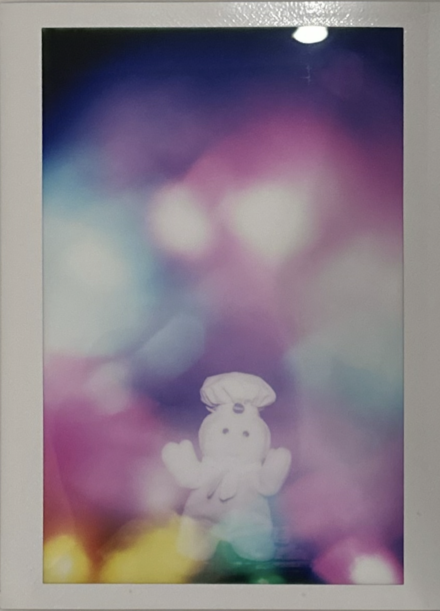
8. used 24 ring rgb. black gaps pattern. used helping hand ran through camera l-bracket. about 2" from lens. used f22 on camera. led brightness 25
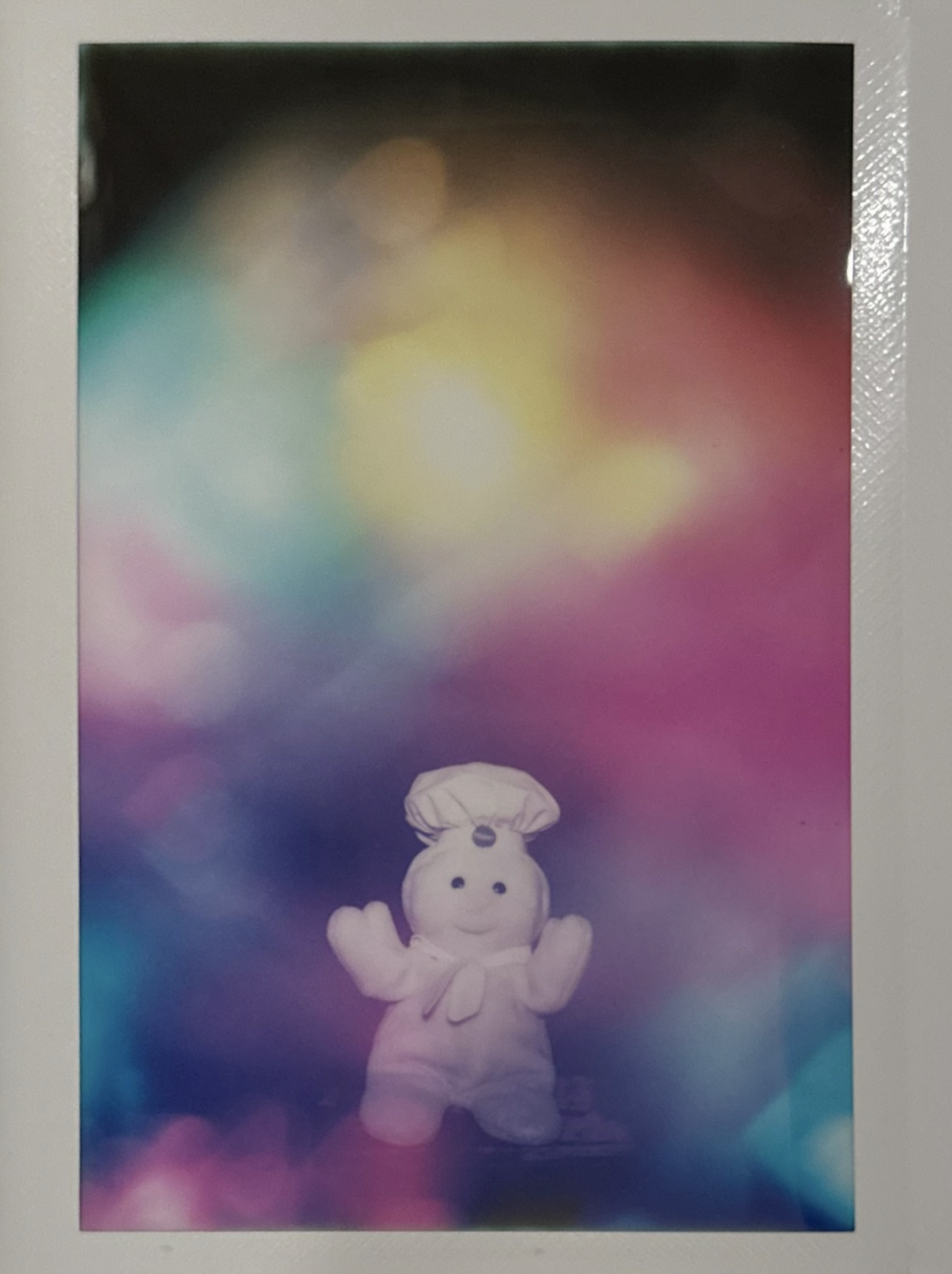
9. used 24 ring rgb. black gaps pattern. 2" from lens. used f22 on camera. led brightness 8
6-29-2026 WEEK 1
electronics
to help with prototyping, solderless connections were prioritized. arduino uno r4 has a direct 4 pin jst sh (jst = japan solderless terminals and the sh is a specific model) connection port also known as qwiic (coined by sparkfun) or stemma qt (conined by adafruit). sensors with the same connections were chosen for simple/reusable cables.
unfortunately, soldering could not be avoided for the leds. bare wires for grounding and power pads will be soldered on and a male to male header wire cut and stripped on one end to be soldered onto the data pad.
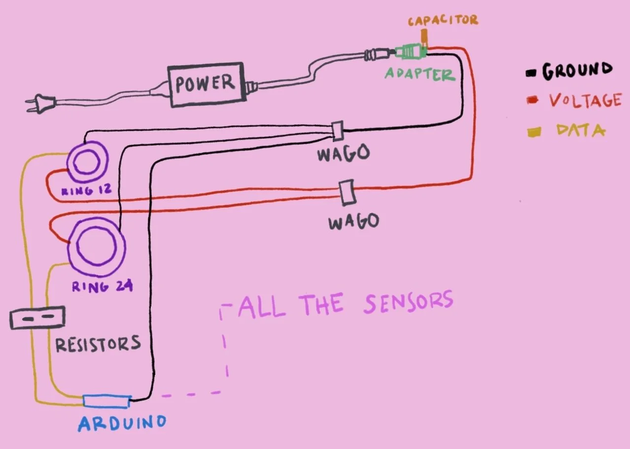
I’m still waiting on parts to arrive to test out the leds. however, in the meantime, here is the hypothetical schematic for how it will be wired. neopixel ring leds draw a lot of current, so they will have their own power supply. I’m unsure how the ring leds will photograph, so this is all conjecture for a two ring layout.
also a note to myself: the leds connect to the arduino’s digital pins d0 - d14 (uses serial1 and not serial, which is for usb-c port).
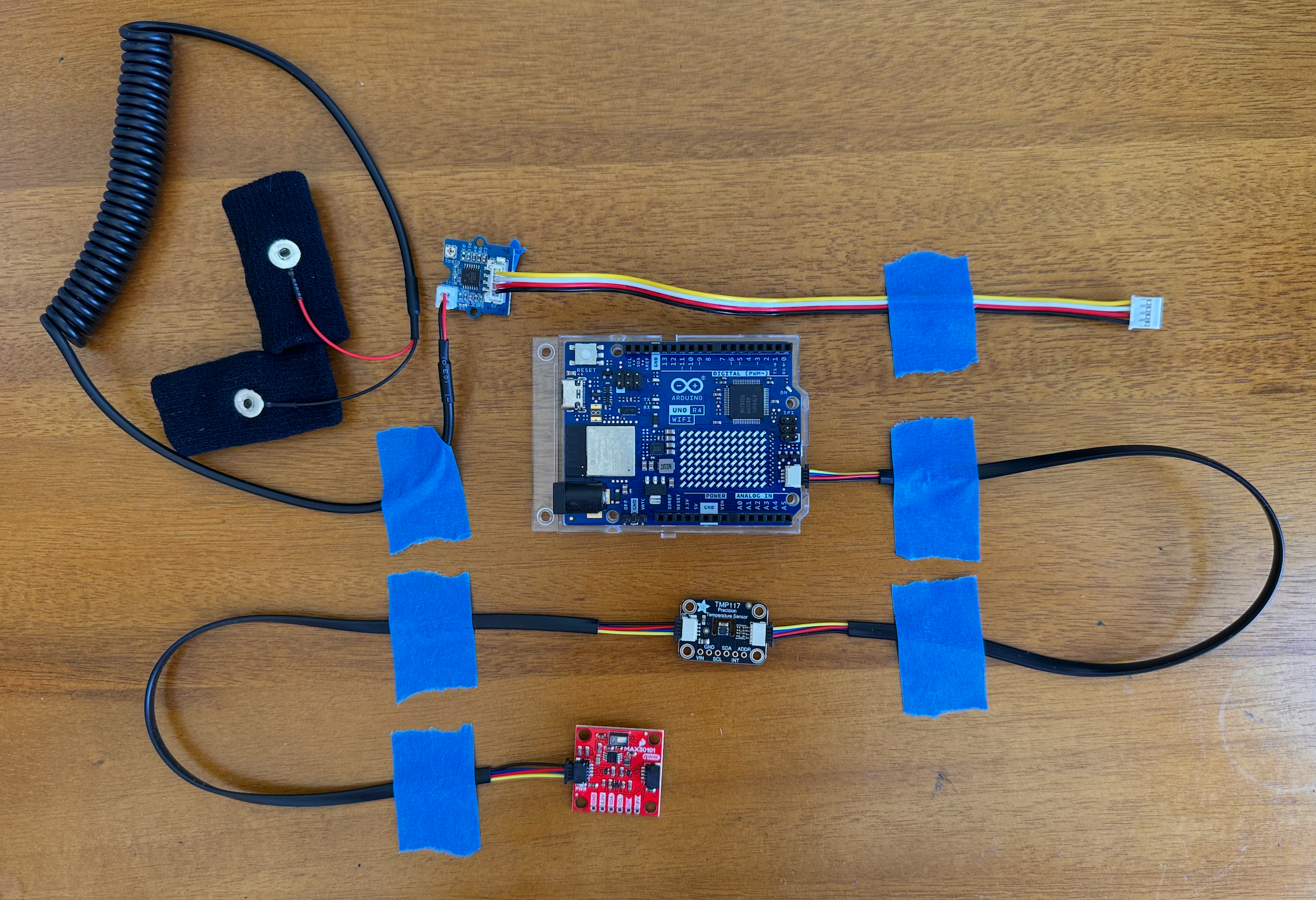
the tmp 117 and max30101 are connected in parallel on the qwiic/stemma qt port on the arduino uno r4.
the grove gsr sensor is awaiting a grove adapter to connect directly onto the arduino with male jumper pins. you can do male to male jumper wires, but I prefer a better fit.
the painter’s tape is just for everything to lay flat for this photo.
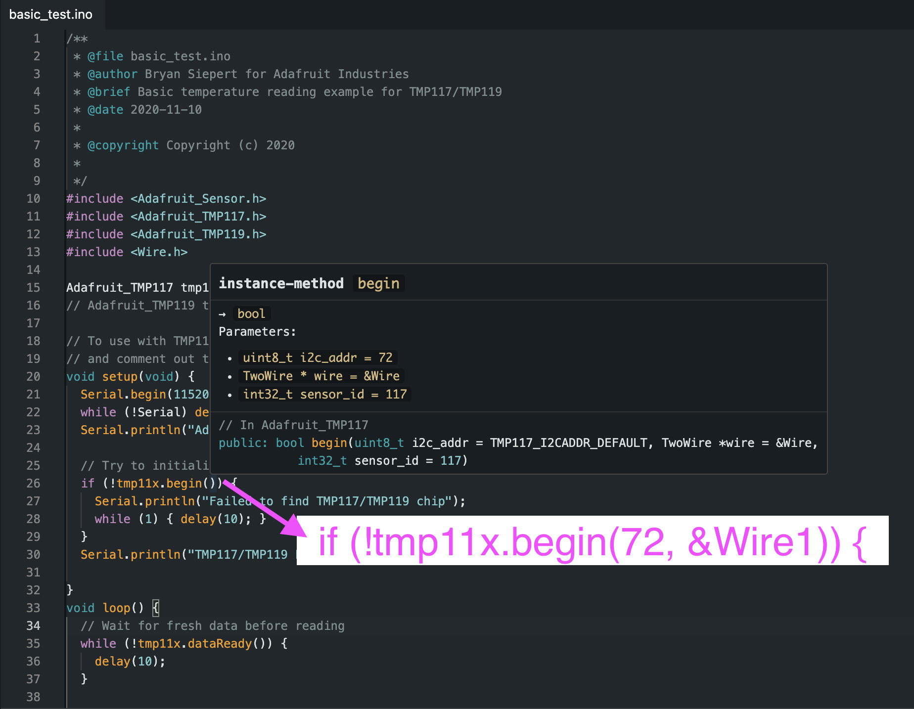
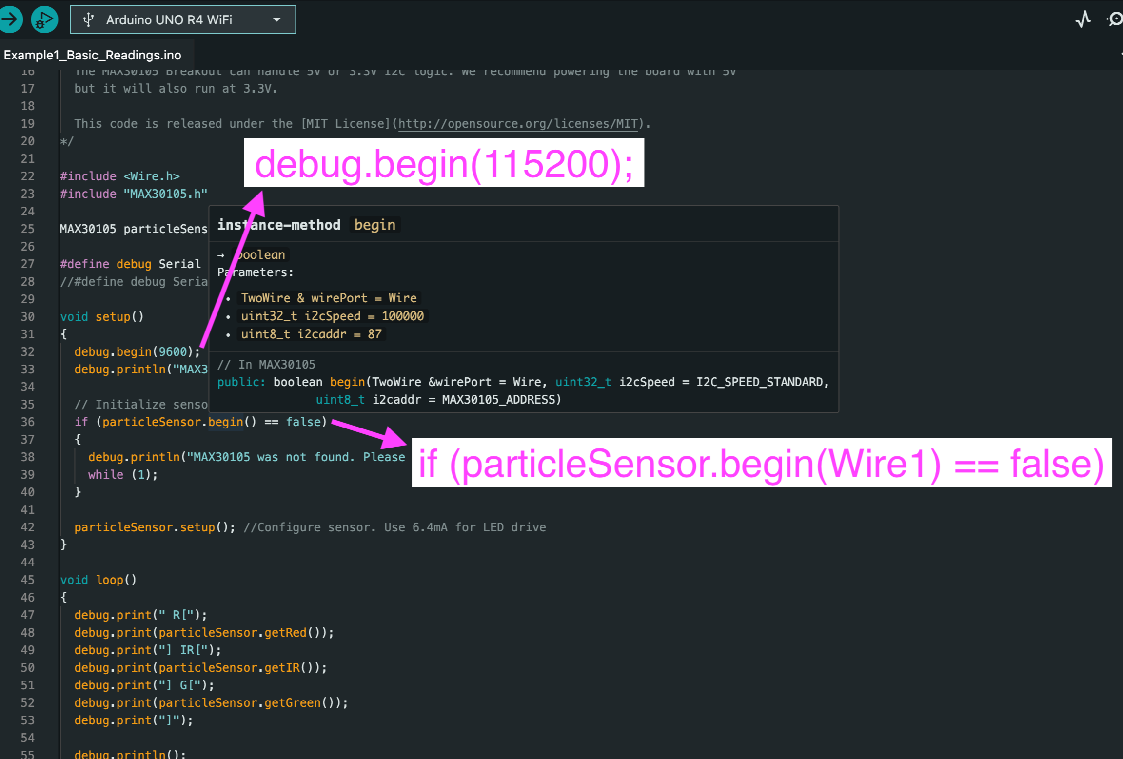
you can test your connections by using the arduino ide. you will need to install the corresponding libraries (adafruit tmp117, sparkfun max3010x pulse and proximity sensor library) for each sensor to get the examples → basic_test code to upload to your arduino to test.
things to note, is qwiic/stemma qt uses wire1 instead of the default wire (for a4/a5 pins), so you will have to change your example code to read off of wire1.
also make sure to change to 115200 baud rate for debugging as the arduino uno r4 allows for higher rates than older arduinos.
about i2c
i2c is short for inter-integrated circuit, it is a communication protocol. arduino has a software library named wire that implements it within a class called twowire (it has two pre instantiated objects wire, and wire1 you can access). i2c starts the transmission (hence the .begin() calls), only targets a specific device by address, transfers data, and stops the transmission.
for i2c addresses, each sensor’s manufacturer has their sensor assigned a number from 0 - 127. you will want unique i2c address for your sensors. I was lucky that the sensors I chose already had different i2c addresses. some manufacturers let you override the address, other times you would connect them to different sections like i2c wire vs i2c wire1.
zits appeared: 5
workouts skipped: 2
🎆 watched: ∞
6-21-2026 WEEK 0
aura camera project
aura cameras are expensive and you cannot purchase them outright. unfortunately, it’s fallen into subscription fee pricing. this project is to find out how far it can be reverse engineered and made open sourced. it will also include the use of a modern biofeedback optical sensor for heart rate variability. plus in the future, have it be paws friendly and potentially use a projector to have auras fill the space - ready to interact with others.
compilation list of parts for camera setup and electronics setup
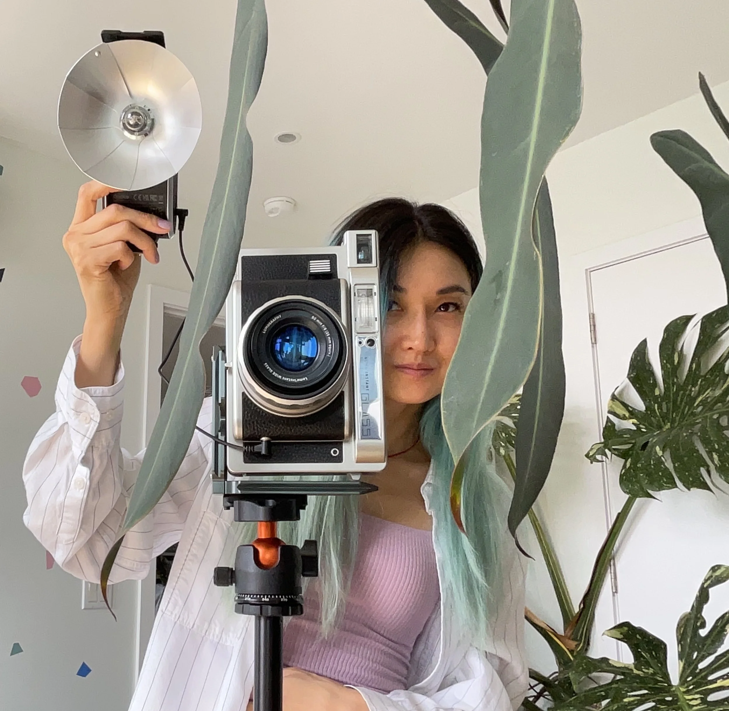
camera setup - tripod, l-bracket, vertically aligned, pc sync cable to external flash.
camera set at fixed shutter speed 1/30 and focus zone set at 1 - 2m.
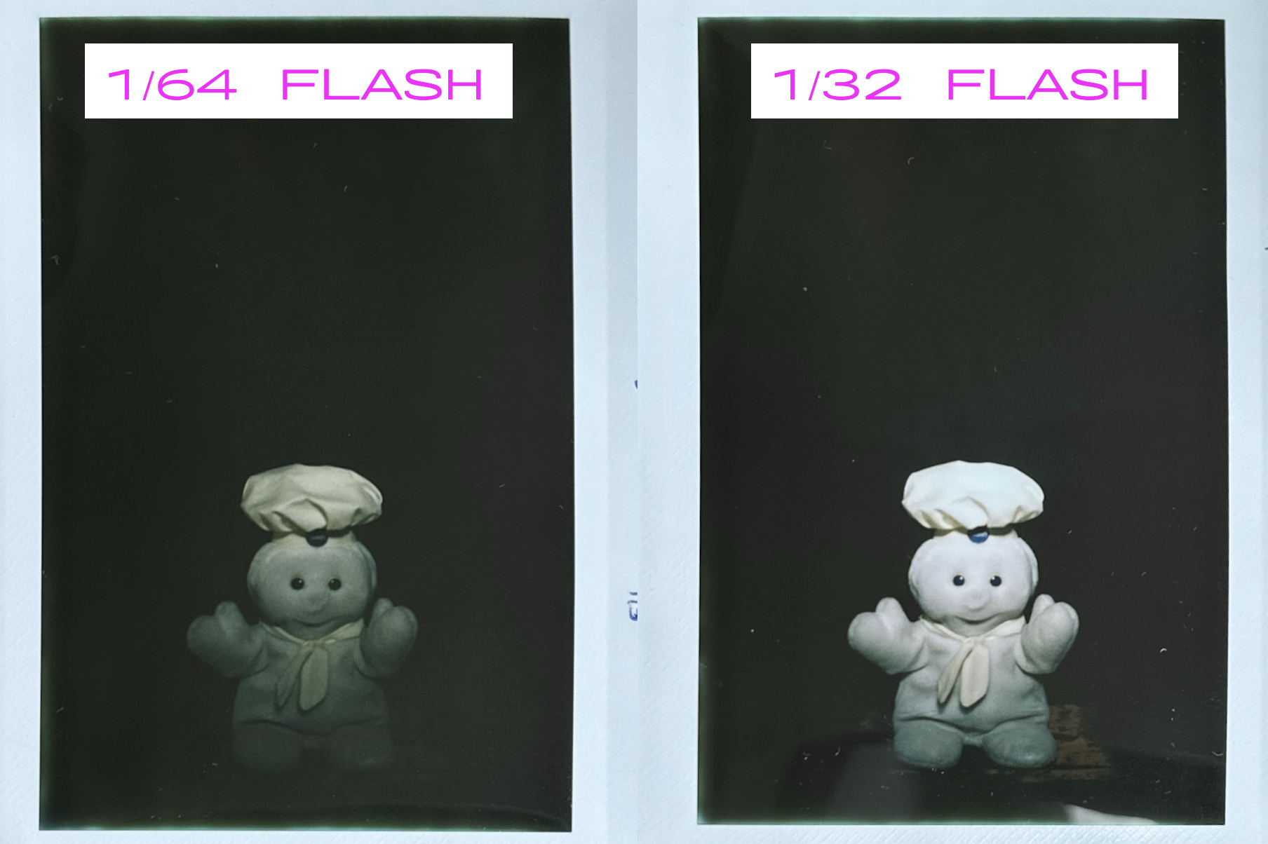
external flash set at manual at 1/64
external flash is used off camera. recommended to be above the lens and pointed downward about 15 degrees to subject known as butterfly/paramount lighting.
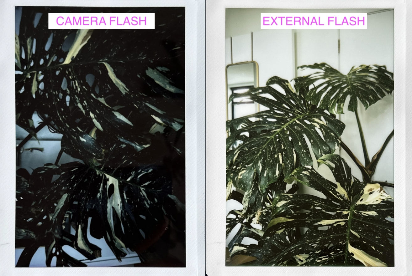
test photos taken with camera’s flash and with external flash. camera’s exposure is set to the default value of 0 in both photos.
🚬 smoked : 0
headache induced: 1
the repair shop watched: ∞